
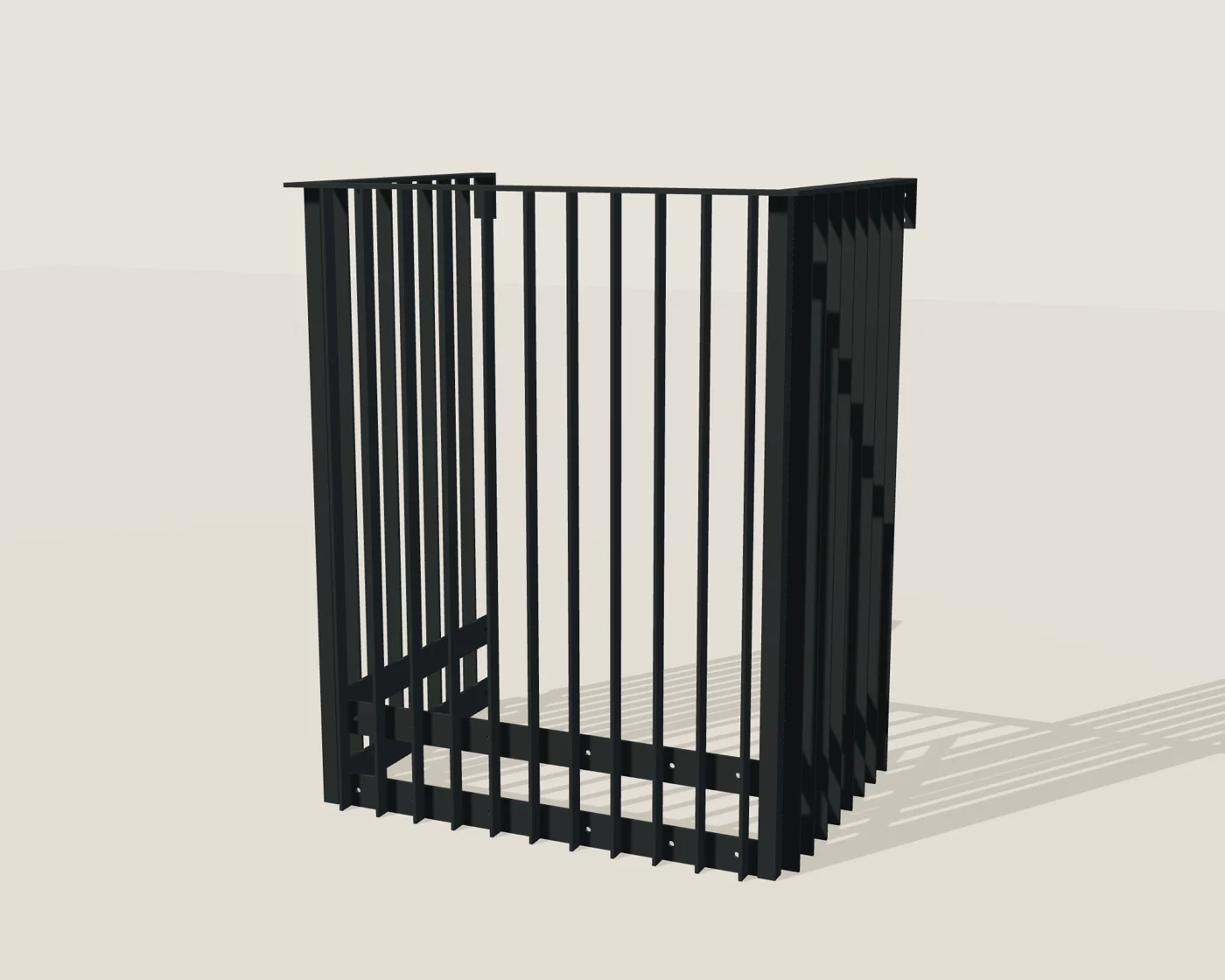
1,200 mm overall width × 900 mm overall projection · steel · isometric geometry
STEP-derived geometry study. Colours identify components; they do not illustrate a coating. Overall mass excludes anchors and coating; handling and delivery need project review.
BALCONY BALUSTRADES / APG
Steel U-shaped balcony balustrades
Continuous flatbar framing. Clean vertical lines. Developed around your project.
No order or payment is taken on this page.
MEASURE THE SPACE
Start with the run and its supports.
Measure the front run and each return. Show both structural wall tie positions, the supporting fascia on every leg, finished walking level, floor build-up and waterproofing.
Send a front photograph, a side photograph and the intended use. We can review the layout and identify the fixing information needed.
Add your project details →Proposed guard height: 1,100 mm above the finished walking surface. Actual support and finished levels must be checked.
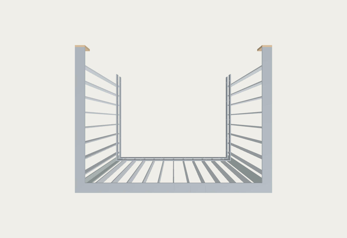
CONTINUOUS WELDED CONSTRUCTION
Two face-welded lower strips.
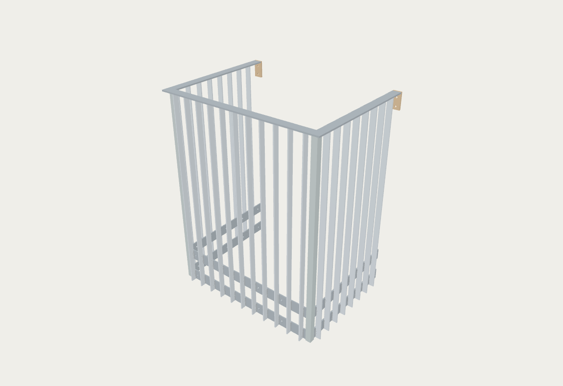
The top rail ties back to a structural wall at each end. Corner rails and strips are mitred and welded as one assembly, without mid-run splices. Both lower strips are on the INSIDE of the uprights, with broad faces vertical and face-welded across the uprights, against the structural balcony fascia.
1 / Confirm the structure and levels.
Check the structural fascia, wall returns and finished floor; include build-up and waterproofing.
2 / Resolve the fixing detail.
Anchor type, plate behaviour and weld specification must match the actual supporting structure. Study fixing holes are not an anchor selection.
3 / Install to verified project drawings.
These geometry illustrations are not installation instructions. A final project fixing and installation detail is required before fitting.
SELECTED CONFIGURATION
Dimensions and construction.
- Selected width
- 1,200 mm overall width × 900 mm overall projection
- Overall front width
- 900 mm
- Top rail
- 60 × 10 mm flatbar
- Uprights
- 40 × 8 mm flatbar
- Two lower strips
- 80 × 8 mm flatbar, inside the uprights against the fascia; broad faces vertical and face-welded
- Nominal steel mass
- 153.5 kg
- Construction
- Continuous welded assembly: mitred corner welds where applicable; no mid-run splice
- Technical status
- Geometry and preliminary calculation studies prepared. Full material, weld, supporting-structure and fixing verification remain outstanding.
All dimensions shown are development dimensions. Fascia fixing levels depend on the actual slab and floor build-up.
Before you enquire.
Can I buy a standard kit now?
These proposed layout sizes are available for project enquiries. Final suitability, fixing details, price and lead time must be confirmed before an order.
What does the selected width mean?
Width and projection are overall outside dimensions. The top rail ties to a structural wall at both open ends; every leg requires structural fascia support below the floor.
Can I request the technical pack?
Yes. Ask for the current geometry and preliminary technical information in your enquiry. Verified fabrication and installation details remain separate requirements.
YOUR PROJECT
Send this configuration.
Steel · 1,200 mm overall width × 900 mm overall projection
Your selections will be included automatically. Add the location, intended use and photographs; ask for help with fixings or the technical pack here.
A different size or layout?
Tell us about corners or an unusual opening so we can review the project.
Steel U-shaped layout draft specification downloads
Draft technical downloads for 8 exact U-shaped assemblies. Overall kit dimensions differ from reference leg and cut lengths. Structural fascia restraint and wall ties at both top ends are required. The lower strips remain on the inside of the uprights, with a 48 mm contact face and 32 mm corner inset. Not for construction or manufacture, NBS approval or tested load ratings. Correlated fixing reactions and actual project actions, substrates, anchors, welds, finish and independent review remain open.
Steel U layout — 900 mm projection
- U-1200-900 — approx. 153.5 kg nominal model mass
- U-1800-900 — approx. 184.1 kg nominal model mass
- U-2400-900 — approx. 211.0 kg nominal model mass
- U-3000-900 — approx. 241.6 kg nominal model mass
Download Steel U layout — 900 mm projection draft ZIP